Dimensioning Sheet Metal Parts Solidworks

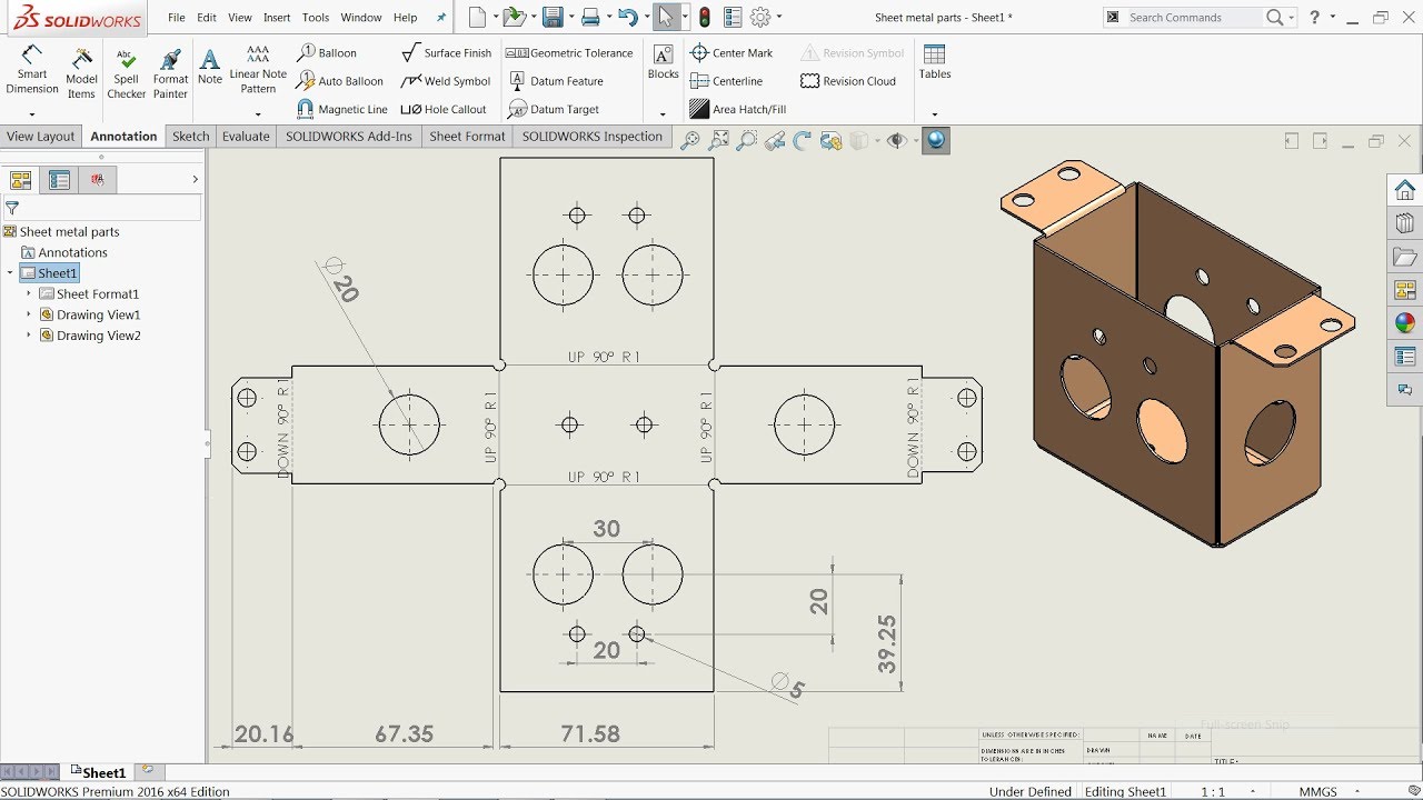
Solidworks Sheet Metal Drawing Tutorial Bend Line Flat Pattern Unfolded Bend Table Punch Table Youtube
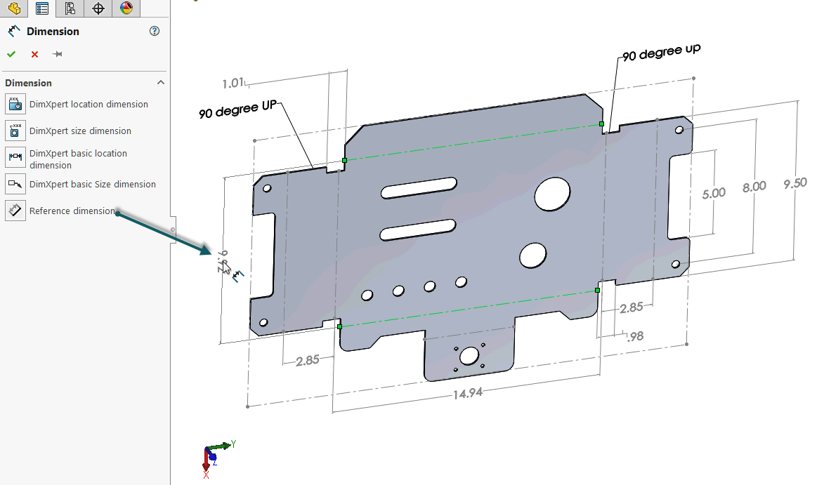
How To Define The Mbd Data Of Sheet Metal Parts Engineers Rule
Solidworks Tutorial Sheet Metal Cone Youtube

Solidworks Sheet Metal Drawings Youtube
2012 Solidworks Help Creating Drawings Of Sheet Metal Parts
How To Dimension The Undimensionable Solidworks Drawing Computer Aided Technology
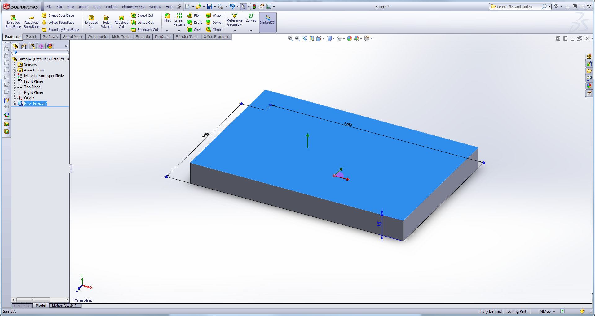
How to model complex sheet metal parts in solidworks.
Dimensioning sheet metal parts solidworks.

What Happened To My Flat Pattern View Computer Aided Technology

Solidworks Sheet Metal Gauge Table And Properties Youtube

Using Solidworks Sheet Metal Functionality Create A B Size Drawing Sheet Metal Drawing Technical Drawing Mechanical Engineering Design

20 Latest Bending Drawing Sheet Metal
Source : pinterest.com
